MCIO Connector Inline Inspection System

The MCIO Connector Inline Inspection System is a fully integrated, multi-stage vision inspection platform designed to deliver end-to-end quality assurance throughout the connector manufacturing lifecycle. This system operates across two major production domains — metal stamping and plastic molding — with strategically placed inspection stations that ensure every connector passes through multiple layers of quality validation before reaching the end of the line.
The system's architecture is designed to address critical inspection goals, such as:
- Early detection of dimensional deviations during stamping
- Pre-molding validation of connector strand integrity
- Final post-molding inspection of aesthetic and structural compliance
The following schematic diagram outlines the key stages of the MCIO Connector Inline Inspection System.
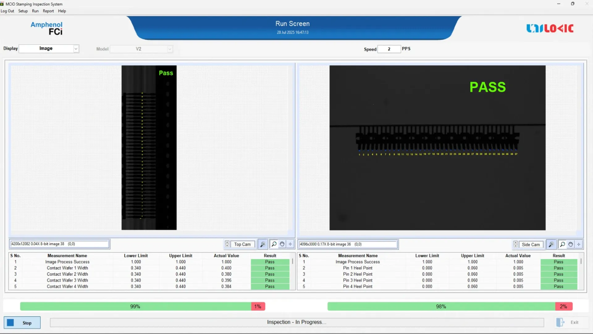
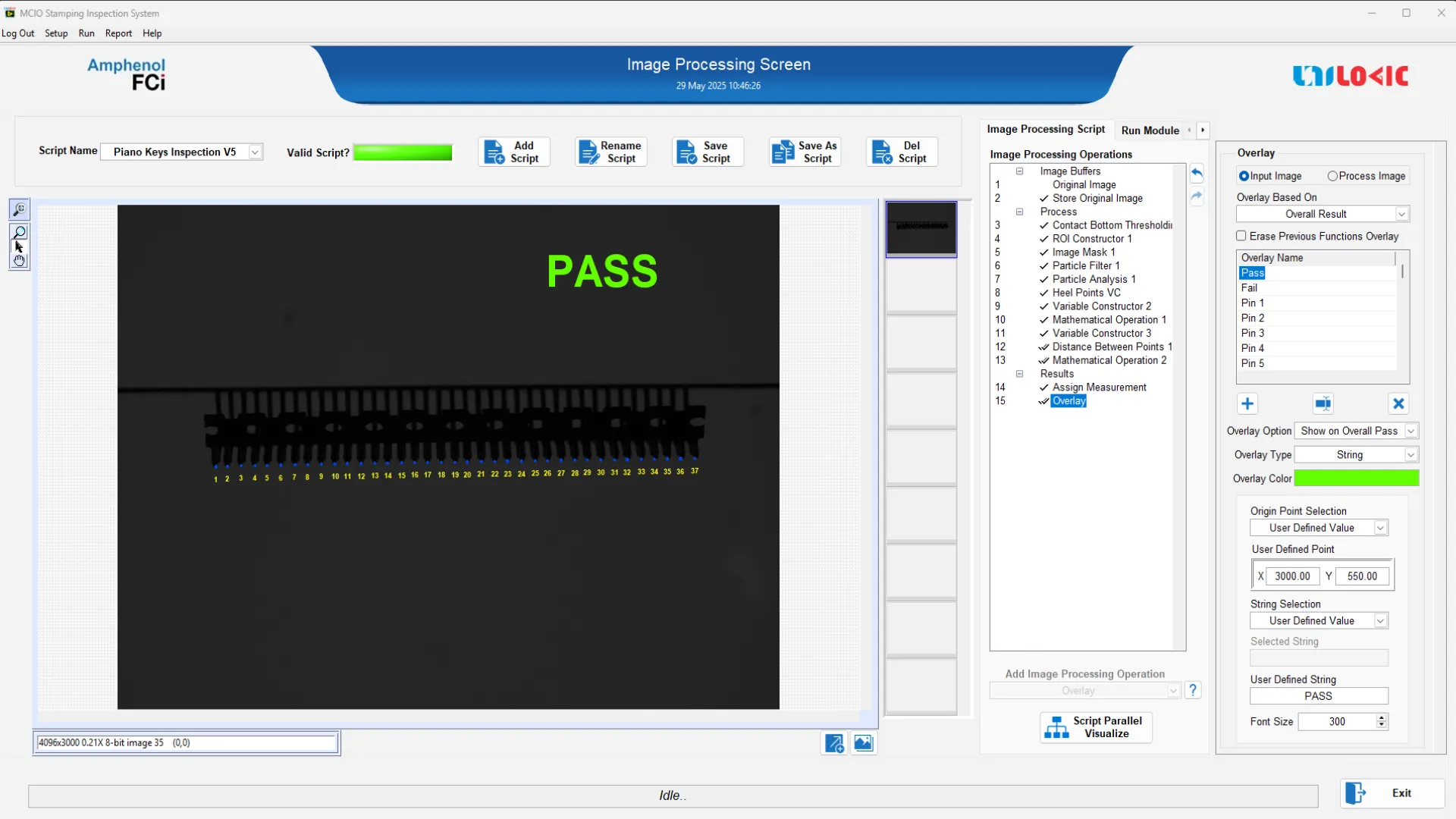
Station 1: Stamping Inspection System
High-Precision Dimensional Inspection of Raw Connector Strands
In the first stage of the process, metallic connector strands are introduced into the stamping station, where the raw terminals are precision-formed using progressive stamping dies. These strands typically contain multiple connector pins with tight dimensional tolerances that must be verified before further downstream processing.
Vision System Configuration
To facilitate inline inspection immediately after stamping, a dedicated vision setup is deployed, consisting of:
- An 8K line scan camera with a 7 µm resolution, paired with backlight illumination, capturing continuous top-view imaging of the strand
- A 20 MP area scan camera with 3 µm pixel resolution, capturing flatness measurements from the front
These imaging components are controlled by custom-developed machine vision software, which performs high-speed image acquisition and executes precise edge detection, feature extraction, and geometric validation in real time.
Inspection Capabilities
- Terminal Pitch Measurement: Ensures consistent spacing for accurate mating and downstream handling
- Terminal Width Validation: Detects malformed or bent terminals
- Pilot Hole Pitch and Diameter Measurement: Verifies feeding holes essential for accurate positioning during molding
- Flatness Analysis: Captures strand profile variations and warpage using front-view imaging
The system operates at a throughput of 750 parameters per second. When a defective part is detected, the machine halts automatically, allowing the operator to remove or cut out the defective part before resuming operation.
Strand Recoil and Transfer
Post-inspection, the validated strands are automatically recoiled into spool units for seamless transfer to the next phase. This mechanism ensures minimal human intervention and maintains strand alignment for consistent feeding into the molding station.
Station 2: Molding Inspection System
Two-Stage Verification: Before-Molding and After-Molding
The second stage comprises two inline inspection sub-stations integrated within the molding unit. These ensure both dimensional compliance before plastic encapsulation and aesthetic integrity after molding.
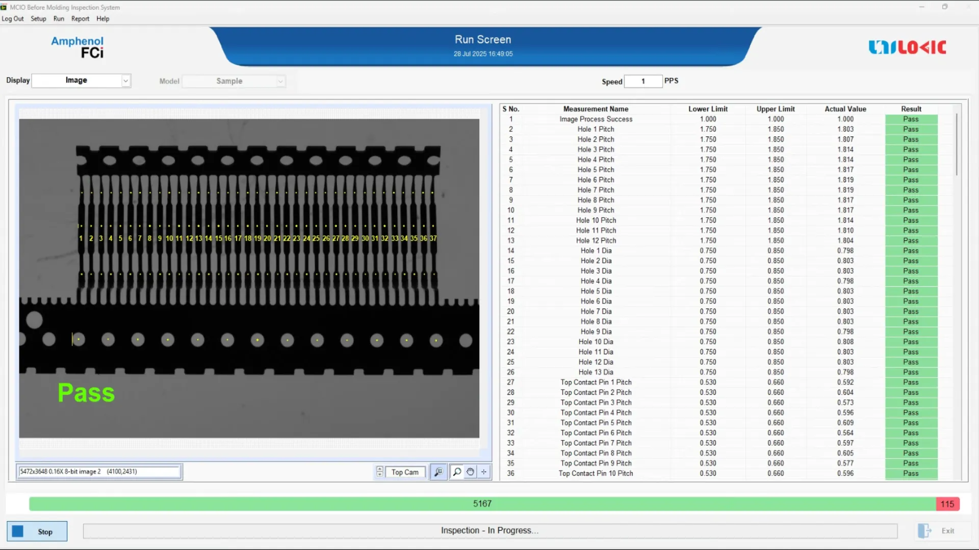
Sub-Station 2.1: Before-Molding Inspection Sub-Station
Although the stamping station provides high-resolution inspection, the pre-molding vision sub-system serves as a secondary validation layer, focusing on critical quality checkpoints just prior to encapsulation. This ensures no mechanical shifts or defects introduced during handling compromise the mold quality.
Key Functions
- Basic pitch and width validation using top-mounted 20 MP area scan camera (4 µm resolution)
- Pilot hole alignment checks to confirm proper registration
- Real-time feedback to halt the line if a defect is found
This station is optimized for 2 parts per second, providing rapid quality validation without compromising cycle time. If a strand fails this validation, a fail signal is triggered, and the corresponding section of the strand is automatically cut off and ejected, ensuring that no defective material enters the mold.
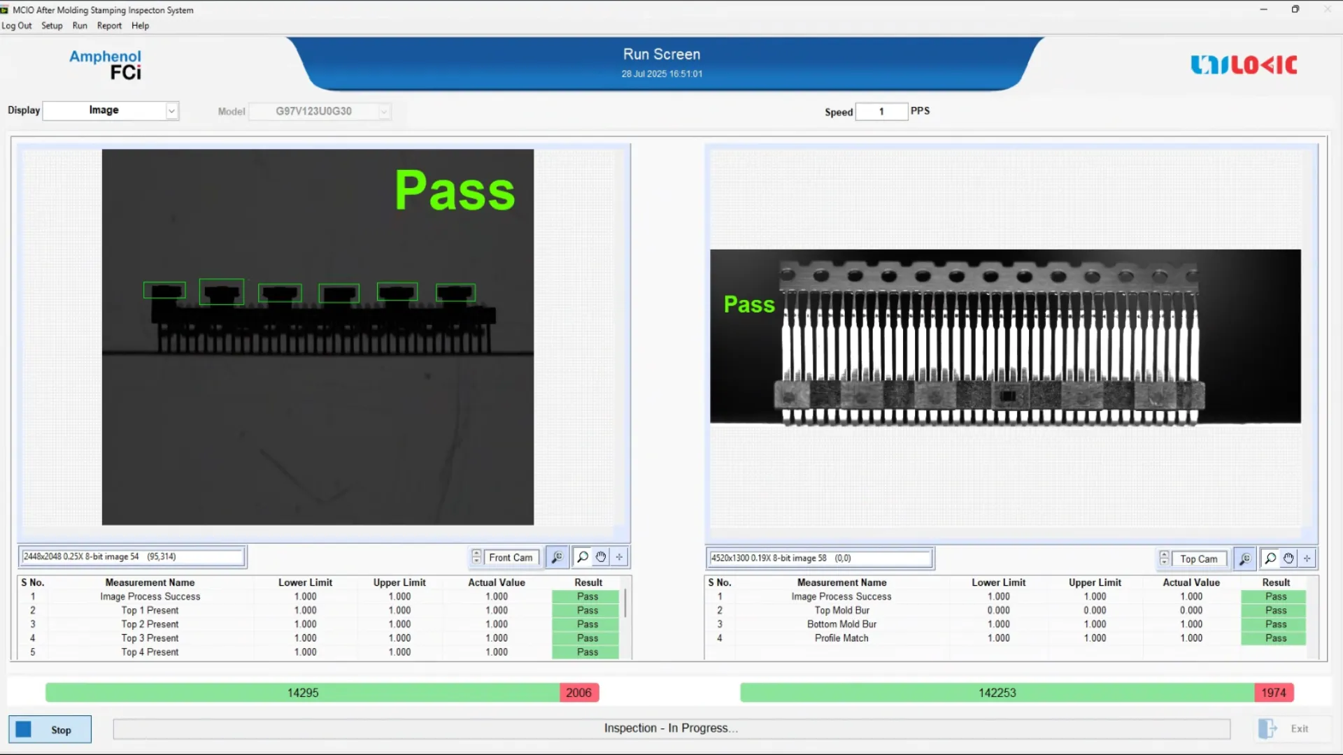
Sub-Station 2.2: After-Molding Inspection Sub-Station
Final Aesthetic and Structural Verification with Dual-Camera Configuration
Following the plastic encapsulation process, the post-molding vision inspection system performs a comprehensive quality assessment of the molded MCIO connectors using a dual-camera setup, engineered for robust aesthetic and structural validation.
Camera Configuration:
- Front Camera: A 5 MP area scan camera, mounted at a shallow angle in front of the connector, is optimized for detecting:
- Mold fill presence – to confirm that the plastic has properly filled the cavity
- Flash defects – indicating material overflow due to mold misalignment or excessive pressure
- Top Camera: A 20 MP area scan camera, mounted directly above the connector, performs high-resolution analysis to detect:
- Burrs – small plastic residues or projections typically around terminal exits
- Overall cosmetic quality, including finish uniformity and contour irregularities
The front camera is paired with diffused back lighting to maximize contrast on vertical mold edges and flash areas.
The top camera uses diffuse ring illumination, depending on part geometry, to enhance detection of fine surface features without glare or shadow artifacts.
This stage operates at 2 parts per second, synchronized with the molding cycle.
If the molded connector fails any visual or structural criteria, the fail classification triggers a mechanized strand-cutting unit, which removes the defective part from the feed line — preventing it from reaching the assembly or packaging area
Station 3: Assembly Line Inspection System
System Overview
The Assembly Line Inspection System provides the final quality assurance checkpoint. Here, both structural and dimensional features are validated with 5–8 µm accuracy before packaging. This stage is critical for detecting pin-level defects and ensuring coplanarity, which directly affect connector mating reliability.
Vision System Configuration
The station is equipped with:
- 3 × 12 MP area scan cameras
- 3 × 20 MP area scan cameras
- High resolution lenses for distortion-free measurements
- Industrial lighting for enhanced contrast on edges, pins, and shell features
- Automated part handling integrated with conveyor systems for 100% inline inspection
Inspection Capabilities
The system executes multiple checks in real time:
- Flatness & Coplanarity – Ensures all pins and component surfaces lie within specified tolerance.
- Lip Gap Measurement – Verifies dimensional consistency of sealing or mating surfaces.
- Shell Leg True Position (TP) – Confirms leg positioning accuracy relative to the connector body.
- Pin Damage Detection – Detects bent, missing, or broken pins with high-resolution imaging.
- Pin Symmetry Detection – Detects pin symmetry with respect to the housing center.
Operational Throughput
- Optimized for inline inspection synchronized with the assembly line.
- Operates at up to 1 parts per second without introducing bottlenecks.
|
S.No |
Parameters |
Stamping |
Before Molding |
After Molding |
Assembly Line |
|
1 |
Inspection Speed |
4-5 PPS |
2 PPS |
2 PPS |
1 PPS |
|
2 |
Line Scan Camera - Resolution |
7 µm Based on 8K line scan camera and 26 mm FOV |
Nil |
Nil |
Nil |
|
3 |
Front Area Scan Camera Resolution |
10 µm Based on 5 MP area scan camera and 26 mm FOV |
7 µm Based on 20 MP area scan camera and 35 mm FOV |
4 µm Based on 20 MP area scan camera and 26 mm FOV |
8 µm Based on 12 MP area scan Camera and 30 mm FOV |
|
4 |
Top Area Scan Camera Resolution |
Nil |
Nil |
6 µm Based on 25 MP area scan camera and 35 mm FOV |
5 µm Based on 20 MP area scan Camera and 30 mm FOV |
|
5 |
Defect Accuracy |
Terminal Pitch - ±2 µm Terminal Width - ±3 µm Pilot Hole Pitch - ±2 µm Pilot Hole Dia - ±3 µm Flatness - ±15 µm |
Terminal Pitch - ±10 µm Terminal Width - ±8 µm Pilot Hole Pitch - ±10 µm Pilot Hole Dia - ±15 µm |
Connector Aesthetics - ±15 µm |
Flatness - ±20 µm Lip Gap - ±12 µm True Position - ±12 µm Pin Damage Detection - ±20 µm Symmetry Detection - ±12 µm |
Benefits
- Full-spectrum coverage of the production line, ensuring early and final-stage quality validation
- Dramatically reduced manual dependency, enabling labor cost savings and consistent quality
- Improved die and mold life due to early defect filtering and precise component engagement
- Inline defect visualization allows for real-time process optimization and tuning
- Productivity: Supported full-speed assembly line inspection without bottlenecks.
- Reduction in customer rejections via continuous SPC-backed quality assurance
- Scalable across multiple connector types with minimal setup changes
- Robust in harsh environments, leveraging industrial-grade components and vibration-resistant mounts
- Operator learning curve minimized through guided UI and visual indicators
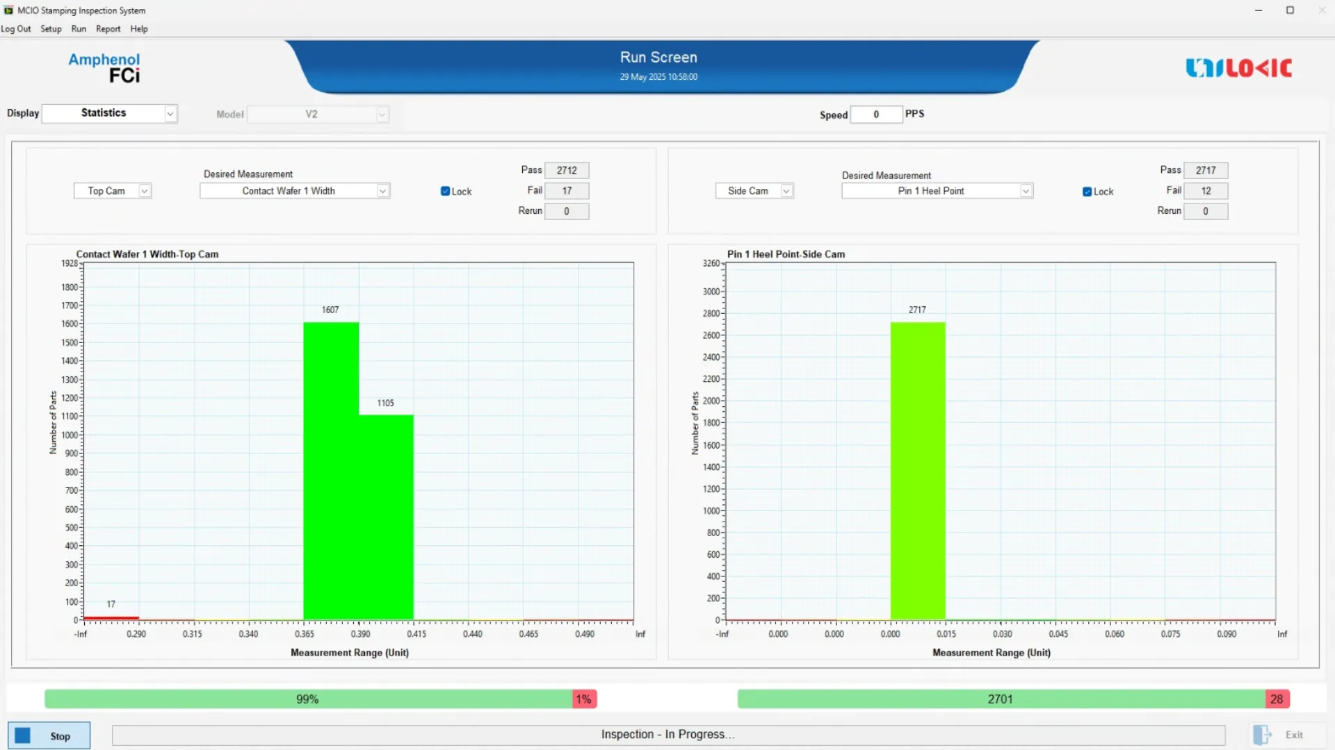
- Data-rich environment for engineers and quality teams to analyze trends and fine-tune process windows
- Ensures compliance with internal QA protocols and external industry standards
Features
- Unified vision control platform for stamping and molding stations
- Dual inspection points at the molding station: pre-molding and post-molding
- Real-time defect classification with integrated decision logic
- Model-based geometry verification for post-molding profile accuracy
- High-speed industrial cameras with sub-pixel resolution accuracy
- Multilayer image filtering: edge detection, shape fitting, contour matching
- Batch-wise inspection traceability with secure access control
- Multiple rejection strategies: auto-cut, operator halt, tagged logs
- Customizable inspection recipes per connector variant or customer requirement
- Visual inspection dashboard for operator-friendly interaction and defect tagging
- Automated daily report scheduling in Excel, PDF, or SQL-backed dashboards.
- Maintenance diagnostics: camera focus status, illumination monitoring, inspection coverage logs
Types of defects identified:
- Terminal width
- Terminal Pitch
- Pilot Hole Pitch
- Pilot Hole Diameter
- Flatness from the front view
- Connector aesthetic after it is being molded
- Coplanarity
- Lip Gap
- Shell Leg True Position
- Symmetry Detection
- Pin Damage in Assembly Line Inspection
Conclusion:
The MCIO Connector Inline Inspection System represents a vision solution for modern connector production lines. By integrating advanced imaging technology and automation from stamping through post-molding, the system delivers reliable, repeatable, and traceable inspection performance.
Its dual-station architecture ensures that only conforming parts pass through each critical stage of production, significantly reducing defects and improving product consistency. With its modular software and hardware design, the system is highly adaptable, making it a vital asset for quality-centric manufacturing environments.