Understanding the Fundamentals of Machine Vision Lenses
In any industrial or automated machine vision system, the lens is a critical component — it determines what the camera sees, how clearly it captures the scene, and how effectively the downstream inspection system performs. A well-chosen lens delivers sharp, distortion-free images that improve automated inspection, test & measurement automation, and the overall accuracy of automated test equipment (ATE). A poor lens choice can reduce clarity, distort measurements, and lead to failed detections in real-world manufacturing environments.
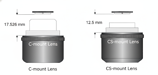
1. Lens Mount
The lens mount defines how a lens connects to the camera and how far the optical flange is from the sensor. This flange-to-sensor distance must match the lens design to maintain correct focus. In machine vision, improper flange distance directly affects inspection reliability in vision systems, automated inspection machines. The two most commonly used mounts are C-mount and CS-mount.
- The C‑mount has a flange-to-sensor distance of 17.5 mm.
- The similar CS‑mount has a shorter flange distance of 12.5 mm.
Why this matters:
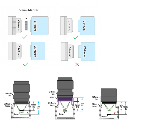
If you use a C-mount lens on a CS-mount camera (or vice versa) without a proper adapter or spacing correction, the focus plane will shift, resulting in a blurry image and a target not accurately in focus.
Additional Note on C-Mount and CS-Mount Compatibility
It’s important to ensure that both the lens and camera mount types are matched correctly:
✅ A C-mount lens fits properly on a C-mount camera, and a CS-mount lens works on a CS-mount camera — these combinations maintain the correct flange focal distance and deliver sharp focus.
✅ If you have a C-mount lens and a CS-mount camera, the focus plane will fall behind the image sensor because the CS mount’s flange distance is 5 mm shorter. In such cases, a 5 mm C-to-CS adapter ring is required to achieve proper focus.
❌ If you have a CS-mount lens and a C-mount camera, the focus plane will lie in front of the image sensor, causing the image to remain permanently out of focus. In this case, even using an adapter will not correct the mismatch.
Also, mismatching mounts may limit the sensor size you can use, or cause vignetting or other optical issues.
Tip: Always check the camera’s mount specification and choose a lens that matches that mount (or you must include the correct spacer/adapter and recalculate working distance).
2. Focal Length
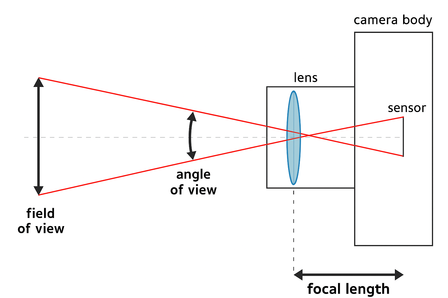
The focal length is the distance between the lens and the image sensor when the subject is in focus.
It determines how wide or narrow the camera’s field of view (FOV) will be.
- A shorter focal length lens gives a wider field of view (captures a larger area) but lower magnification.
- A longer focal length lens gives a narrower field of view, higher magnification (zoom-in effect), and tends to require more space (longer working distance) or smaller FOV.
In machine vision, however, we often use it in relation to working distance (WD) and field of view (FOV) to pick a lens for a specific application.

Example Calculation:
Given:
- Sensor Size = 8.8 × 6.6 mm
- Field of View = 106 × 80 mm
- Working Distance = 145 mm
Calculation:
Focal Length = ( 145 / 80 ) * 6.6 ≈ 12 mm
Hence, ~12 mm focal length is suitable for the given example.
Refer to our Lens Selector and try your applications to get your required focal length lenses.
Similar Cases (Reference Applications)
The following real-world implementations demonstrate how focal length selection varies with field of view and working distance:
- Large FOV Inspection (400 × 300 mm):
A 16 mm focal length lens was used at a working distance of 566 mm with a 20MP camera, resulting in reduced image distortion and stable inspection performance.
Explore our case study from ToothBrush Inspection System - Small FOV Inspection (20 × 16 mm):
A 75 mm focal length lens was selected, along with a working distance of 201 mm and a 5MP camera, to achieve higher magnification and precise feature detection.
Explore our case study from Clip Inspection System
Practical considerations:
- When the working distance is increased, a longer focal length may be required to maintain the same field of view (FOV). In such cases, adequate illumination must be ensured, as light intensity decreases with increasing working distance.
- Conversely, when the working distance is reduced (by bringing the lens closer to the object), a shorter focal length (wider lens) may be needed to maintain the same FOV.
Changing the FOV requirement changes the required focal length.
3. Aperture
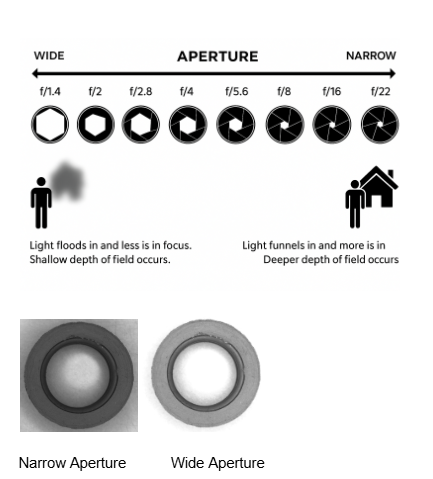
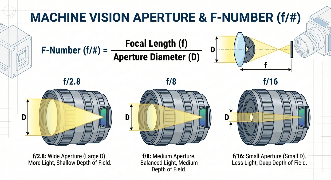
The aperture, also known as the iris, is an adjustable opening inside a lens that controls how much light passes through to the camera sensor. Similar to the pupil of the human eye, the aperture can open wider to allow more light in or close down to restrict light.
In machine vision systems, the aperture is typically specified using an f-number (f/#), such as f/2.8, f/8, or f/16, which represents the ratio between the lens focal length and the diameter of the aperture opening.
The iris plays a key role in
- image brightness,
- depth of field,
- sharpness, and
- measurement accuracy.
A larger aperture (smaller f-number) allows more light → brighter image but shallower depth of field (less of the scene in focus).
A smaller aperture (larger f-number) allows less light → darker image but greater depth of field, which is useful for seeing more of the object in focus, especially when it has uneven heights or curved surfaces.
Why this matters in machine vision:
- In low-light or high-speed setups, you might need a larger aperture to let in enough light for the exposure — but you risk parts of the image being out of focus.
4. Compatible Sensor Size
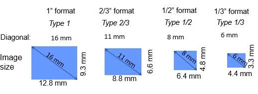
Machine vision sensors are categorized as 1/3", 1/2", 2/3", 1", etc.
However, these names are legacy values — the actual image sensor area is smaller.
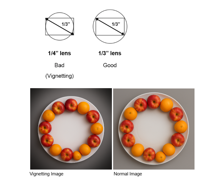
Every lens projects an image circle.
If the sensor is larger than the image circle → vignetting, dark corners, distortion.
Matching lens-to-sensor size is critical in high-resolution systems (e.g., 12 MP, 20 MP, 25 MP), Always verify the lens’s supported sensor format before selection.
Note: The inch-based sensor format naming convention dates back to early video tube technology. Although the naming persists, the actual light-sensitive area of modern sensors is smaller than the stated size.
Every lens is designed to project an image circle — a circular image of a given diameter that fully covers the sensor without dark corners (vignetting) or excessive distortion. Hence, the sensor size you pair with the lens is crucial.
If the sensor size is larger than the image circle a lens can handle → edges of the sensor may receive incomplete image data (dark corners, vignetting), reduced resolution or distortion.
Important matching checks:
- Check the lens datasheet: what format size is it designed for (e.g., 1/2″, 2/3″, 1″)?
- Compare the camera’s sensor format (diagonal, horizontal/vertical mm) and ensure the lens’ image circle is sufficient.
- Remember: “1″ format” in machine vision does not literally mean a 1 inch sensor diagonal; it is a naming convention. Better to check physical mm dimensions (e.g., 16 mm diagonal).
5. Types of Machine Vision Lenses
Machine vision applications require different types of lenses depending on factors such as working distance, field of view, accuracy, object size, and measurement precision. Selecting the right lens type is essential to achieve reliable image quality and accurate inspection results.
Below are the most commonly used lens types in industrial machine vision systems.
1. Fixed Focal Length (Prime) Lenses
Fixed focal length lenses have a single, non-adjustable focal length (for example, 12 mm, 16 mm, or 25 mm). They are widely used due to their:
- High optical resolution
- Low distortion
- Excellent image stability
- Rugged design suitable for industrial environments
- Cost-effectiveness compared to specialized optics
These lenses are ideal when the camera position and field of view remain constant.
✅ Example (Real Application)
Bearing Seal Inspection System
In our bearing seal inspection system, fixed focal length lenses are used for both the top and bottom cameras to achieve highly accurate dimensional measurements and consistent image quality.
Case study: Bearing Seal Inspection System
2. Telecentric Lenses
Telecentric lenses are specialized optics designed to maintain constant magnification regardless of object distance (within a defined working range). Unlike conventional lenses, they capture light rays in parallel, which eliminates perspective errors.
Key advantages:
-
Maintains constant magnification regardless of part height variations within the working range
-
Eliminates perspective and parallax errors for accurate dimensional measurement
-
Ideal for high-precision gauging, edge detection, and metrology applications
-
Improves measurement repeatability and inspection accuracy
Typical use cases:
Dimensional inspection, component measurement, and high-precision automation systems.
✅ Example (Real Application)
Stainless Steel Ring Inspection System
In our stainless steel ring and flange inspection system, a telecentric lens is used to accurately measure rings and flanges of different sizes and heights, ensuring consistent magnification and precise dimensional analysis.
Explore similar use cases which is as follows
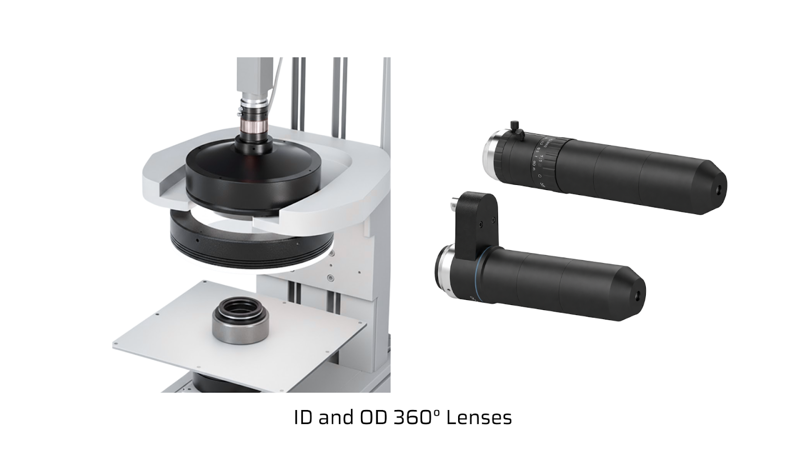
3. ID and OD 360° Lenses (Panoramic Lenses)
ID (Inner Diameter) and OD (Outer Diameter) 360° lenses are specialized optics designed to capture a complete 360-degree view of cylindrical objects using a single camera. These lenses “unwrap” the circular surface into a flat image, allowing the entire inner or outer surface to be inspected in one shot.
Key advantages:
-
Enables full 360° ID/OD circumferential inspection using a single camera
-
Eliminates the need for multiple cameras or part rotation mechanisms
-
Ideal for detecting surface defects, printing errors, cracks, scratches, and contamination
-
Simplifies system design while reducing hardware cost and integration complexity
These lenses are especially valuable on high-speed production lines, where complete surface coverage and reliable inspection are required.
✅ Example (Real Application)
Valve Stem Seal Inspection System
In our valve stem seal inspection system, ID and OD 360° lenses are used to inspect both the inner and outer surfaces of the component in a single capture. This enables complete circumferential coverage of the part, allowing the system to detect surface defects reliably
Case study: Valve Stem Seal Inspection System
4. Other Specialized Machine Vision Lenses
In addition to standard lens types, several specialized lenses are used for niche applications:
(i) Macro Lenses
Designed for close-up imaging of very small objects, such as electronic components, micro-mechanical parts, or surface defects.
(ii) Liquid Lens / Autofocus Lenses
Used when rapid focus adjustment is required, such as in systems inspecting objects at varying heights or on moving conveyors.
(iii) High-Resolution / Large-Format Lenses
Designed for 1″ sensors and larger, or multi-megapixel cameras, ensuring sharp imaging across the full sensor area without vignetting or loss of detail.
(iv) Zoom Lenses
Zoom lenses offer a variable focal length (for example, 8–48 mm), allowing the field of view to be adjusted without moving the camera. Zoom lenses offer flexible framing, allow easy setup and fine-tuning during installation, and are especially well suited for prototype systems or applications with changing requirements.
Conclusion
Selecting the right lens is one of the most important decisions in any machine vision or automated inspection system. The five fundamentals — mount, focal length, aperture, sensor size, and lens type — define image quality and overall inspection performance.
Understanding these parameters helps ensure:
- Proper magnification and focus
- Accurate detection and measurement
- Reliable performance in real production environments
With the right lens choice, inspection accuracy improves across applications like O-ring inspection, connector vision systems, stamping inspection, EV module testing, and more.